 |
|
|
Intellivision Games Software Hardware Overlays Trade Lists Other Stuff |
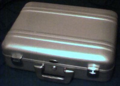
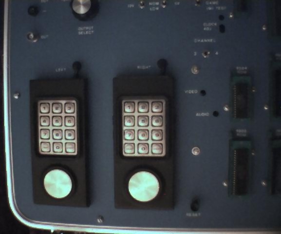
Lady Luck smiled upon me one day, and this contraption fell into my lap. In fact, it's basically the reason why this site exists - and how I've ended up delving far deeper into Intellivision arcana, lore, variants, history, and technical info than I'd ever expected. The IMI Tester-MTE100 is a fully functional Intellivision test bed. The images below show some of the features. As received, the package included:
Scans of the materials can be made available upon request. So, was this a test unit used by the Mattel Service Centers back in the day? Anyone who may have information about this please send a message! These are some basic images of the tester and its guts. Someday I hope to take better ones than what a $20 JamCam allows. Yes, I do have a better camera, but just haven't taken the time. Click an image to see a larger view.
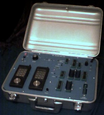
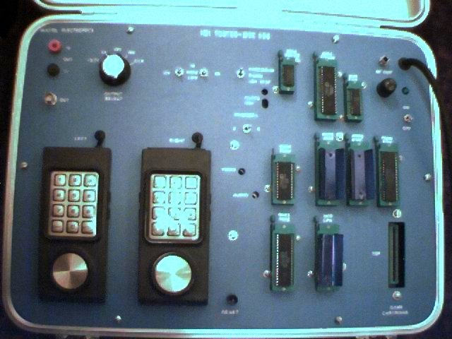
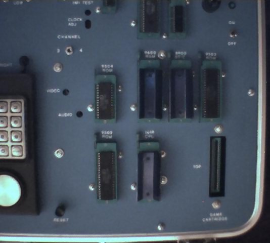
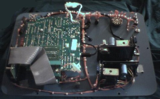
Opening the unit didn't uncover much surprising content. It did reveal that this was a very well-made item, though - definitely built by a pro. I haven't traced all the wiring, but it seems that the design for this is pretty straightforward. The main board is just a regular 2609 motherboard, but all of the DIP sockets are pulled, and orange wires run to the ZIF sockets mounted on the faceplate. It seems the biggest variation from standard Intellivision hardware is in the power supply and conditioning circuit. There are two transformers, and the circuitry is distributed across a couple of mounted planes, sitting under the controllers. The controllers are securely mounted, and there's no hope of loosening them up to treat this as a game machine - which would be a sin anyway. A ribbon cable connects the top-mounted cartridge port to the main unit via an edge connector. What's interesting here is how the MTE-201 is built in. It seems that there's just the PCB from an MTE-201 in here. Is it a ROM variant? To connect this built-in test cartridge, another edge connector was added to the mainboard, with the bottom row of pins clipped off. The other row is wired to the same pins as the "default" cartridge port. I haven't traced the three-way Checksum/Game/Test switch circuitry in detail yet. I can say that in Checksum mode, one controller's pins are shorted such that the MTE-201 is forced into the Checksum test. It does not appear that a new test ROM variation is to be found here... A dump is necessary! The Checksum/Game/Test switch also seems capable of switching which cart is used by shorting (or not) pin 37 of the MTE-201's cartridge port edge connector to pin 38 of the main connector. I haven't quite figured this out yet. This is certainly an interesting piece of hardware, but I do have some questions:
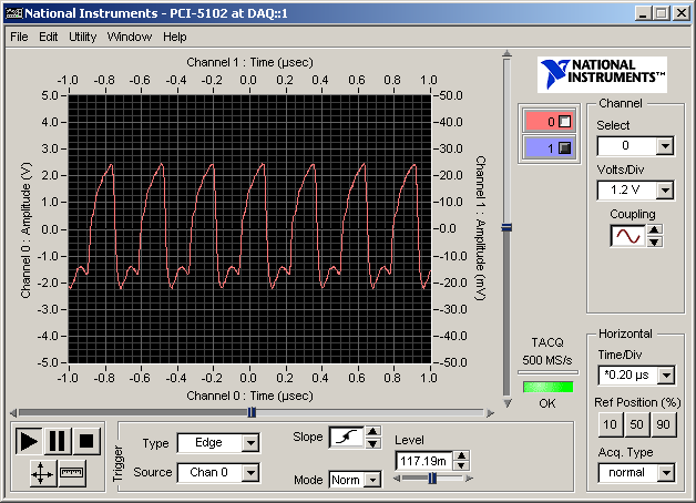
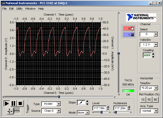
The following measurements were taken using a PCI-based 15 MHz oscilloscope data acquisition plug-in board. (Basic info about the board is here.) I didn't bother taking a bunch of DC voltage measurements, since they aren't really all that interesting, nor did I take measurements at different voltage stress test levels. These tests were run using the chips that came in the unit.
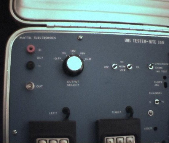
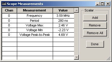
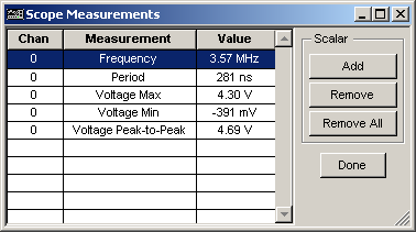
You see that the clock signal is not all too close to the ideal square wave that one assumes. Such is life. The crystal on the motherboard, according to the system schematic, runs at 7.15909 MHz (which is twice the NTSC color subcarrier frequency). The color chip produces a clock signal used by the Standard Television Interface Chip (STIC) to drive the video - and it seems that this is the clock signal measured by the CLK output. I haven't inspected the circuitry to verify this, but it doesn't make sense for this to be any other signal. Using some of the measurement features of the software that shipped with the scope board used here, we can quickly see that we at least have a functioning color chip (General Instruments AY-3-8915) inasmuch as the generation of the bus clock is at the NTSC color subcarrier frequency. We can also see that it's a TTL signal. (w00t!)
For what it's worth, here's a snapshot of one of the other voltage measurements you can select on the tester. 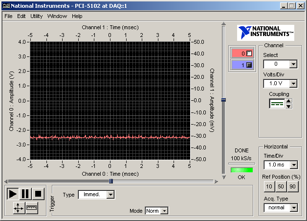 And, as hoped, the -2.1V setting on the tester yields a DC voltage at ... near -2.1 Volts! Quite a bit of noise on there! |
|||||||||||||||||
|
|
Page last updated 19-Nov-2017 04:37:26 UTC |